#Arduino PIR sensor tutorial
Explore tagged Tumblr posts
Visit Tumblr Blog
Explore Tumblr blogs with no restrictions, modern design and the best experience.
Last Seen Tumblr Blogs


Fun Fact
Tumblr has a 66 index score for customer satisfaction in the US.
Text
youtube
Proximity sensing is a very common application in electronics. There are several ways to accomplish this. The most common way is by using a PIR sensor. PIR Sensor senses the change in ambient infrared radiation caused by warm bodies. I have already covered this in my Tutorial No. 5: "PIR Sensor Tutorial - With or Without Arduino". However, since PIR sensors detect movement from living objects, they can generate false alarms. These sensors are also inefficient in hot environments, as they rely on heat signatures.
The other common methods of proximity sensing involve, using reflected ultrasonic or light beams. Using these sensors, the intruding object is detected by the reflected beam back to its source. The time delay between transmission and reception is measured to calculate the distance to the object. In this tutorial, we are going to look at another method of proximity sensing using "Microwaves" and "Doppler Effect". In my hand is an inexpensive RCWL-0516 Microwave Radar Motion Sensor. The RCWL-0516 microwave sensor detects "any movement" from "any object" and does not rely on heat, making it more reliable in hot environments. I am going to use this sensor to create a Geo-fence around my house to detect motion and get notifications.
3 notes
·
View notes
Text
Arduino Projects
Arduino is a platform for open-source electronics that integrates software and hardware. Its integrated development environment (IDE) and programmable microcontroller board make coding and debugging easier. Its adaptability, affordability, and the vibrant developer community that constantly adds to its ecosystem are the main reasons for its appeal.
Beginner-Friendly Arduino Projects
The traditional "Hello World" of Arduino projects is LED blinking. By programming an LED to blink at various times, you may learn how to control it.
Temperature Monitor: Real-time temperature data are shown on a basic LCD screen using a temperature sensor.
Motion Detector: To build a simple motion-detection system, combine an Arduino board with a PIR sensor.
Components Commonly Used in Arduino Projects
Sensors include motion, light, gas, temperature, and humidity.
Actuators include relays, servos, and motors.
LED, LCD, and OLED displays.
Modules for communication: RFID, GSM, Bluetooth, and Wi-Fi.
Resources to Kickstart Your Arduino Journey
The official Arduino website offers thorough instructions and tutorials.
YouTube Channels: A wealth of detailed video lessons for all abilities.
Forums and Communities: Sites such as Reddit and Arduino.cc offer helpful assistance.
Online courses: Structured learning pathways are available on websites such as edX, Udemy, and Coursera.
Arduino projects are a prime example of ingenuity and originality, enabling people to realize their ideas. Arduino provides countless options for experimentation, learning, and development. regardless of your level of experience. For example, you can study the fundamentals or take on challenging tasks.
Explore the world of Arduino now to realize your creative potential and produce something truly remarkable. Your imagination is the only restriction!
To know more, click here.
0 notes
Video
youtube
DIY - Automatic Garage Light
Has this ever happened to you? You come back from a romantic dinner date and when you open the shutter door of your garage you realize that you left the garage light ON. You spent few hours outside with your partner to impress her and all the time this light bulb was on. You immediately turn around and look at her face to see a silent anger on her face. Alright, enough of that. So, in this tutorial I am going to turn on and off the garage light using a PIR sensor. When the sensor detects a moving object, it turns on the light bulb and when the moving object is gone, it turns it off. Lastly, I am going to make sure that light bulb only turn on during the night time (when its dark).
#pir sensor home automation#Automatic Garage Light#automatic on off light bulb#Automatic Garage Light Project#home automation#Arduino and PIR Sensor#automatic passage light#Automatic staircase light#Arduino PIR sensor tutorial
0 notes
Text
In Tinkercad circuits, choose sensor substitutes.

Tinkercad Circuits has a small library of frequently used electronic parts by design. Beginners may easily explore the complexities of the electrical world without feeling overwhelmed thanks to this curation. The drawback is that you can't build an identical replica of your circuit in the simulator if you're looking for a particularly specific part number or version of a sensor that isn't there in the parts drawer.
Fortunately for all of us, there's usually a solution to represent your missing component by using a similar one instead. A few major groups of sensors contain many similar sensors. You can choose an appropriate replacement for your Tinkercad Circuit with the aid of this tutorial.
Digital sensors

As they are activated, analogue sensors provide a changing voltage and resistance. Potentiometers are the most common sort of analogue sensor, but other more specialised varieties exist as well, such as flex sensors, photoresistors, microphones, some temperature sensors, force-sensitive resistors (pressure sensors), piezo components, and some IR distance sensors. Analogue inputs can be read using Arduino's analogRead() function or Tinkercad's "read analogue pin" block.
We advise using a potentiometer or TMP36 temperature sensor as an alternative in Tinkercad circuits if the analogue sensor you wish to use has three pins, as they both have three pins (power, ground, and signal). The TMP36 requires a regulated power supply voltage (2.7-5.5V), whereas a potentiometer is an only resistive sensor. This is an important distinction to make.
The only viable alternative in Tinkercad Circuits if your analogue sensor only has two pins is a two-pin photoresistor (the piezo element in Tinkercad Circuits can only be used as an output).
Electronic Sensors

High/low voltage signals and more complicated digital signals are the two primary categories of digital sensors.
Pushbuttons, switches, tilt ball sensors, magnetic reed switches, PIR motion sensors, and vibration switches are a few examples of sensors in this category. Try one of the many switches and pushbuttons available in Tinkercad Circuits, but also have a look at the tilt sensor and PIR motion sensor, whose simulations might more precisely resemble whatever digital sensor you are trying to replicate. Using digitalRead();, Arduino may read signals with high or low voltage. "Read digital pin" is the Tinkercad block for digital inputs. Launch the simulation below, then click on each sensor to see what happens:
The swap possibilities are more constrained for more sophisticated sensors that make use of data protocols like i2c. There isn't a component that can act as your i2c device, yet you might be able to use the extra library by putting it into your Arduino sketch.
Further Resources
When you make a substitution, we advise using the annotation tool to put notes on your circuit. Even though you couldn't illustrate the precise correct component, this can still aid in communicating the intent.
Don't overlook Tinkercad Circuits' starters, which can get you up and going with several fundamental sensors very quickly (in the components drawer).
Try out our beginner-level Arduino courses using Tinkercad Circuits to learn more about how to add sensors into your Arduino projects.
Send the team your requests for components, please! Although we deliberately limit the number of available components, we are constantly considering what we can add to make Tinkercad Circuits even better. Your criticism is a gift. I'm grateful.
1 note
·
View note
Text
Assignment 3
Proximity Sensor Research
The sensor that I picked for this week was a PIR Motion Sensor!
It allows you to sense motion, (most of the time it is used to detect whether a human has moved in or out of the sensor’s range. Advantages include them being small, inexpensive, low-power, easy to use and not wearing out.
They are commonly found in gadgets and appliances used in homes or businesses.
How it works: Passive infrared (PIR) sensors use a pair of pyroelectric sensors to detect heat energy in the surrounding environment. These two sensors sit beside each other, and when the signal differential between the two sensors changes (if a person enters the room, for example), the sensor will engage.
Brainstorm of ideas! (PIR motion sensor)
1) LED light motion-based color fade change: In parties for example, LED lights are often used to bring life to the party. It would be cool if LEDs wrapped around pillars, plants, furniture etc, could change the color combinations depending on a person walking past the object.
2) Burglar alarm system: I feel like this one makes sense and is pretty straight forward
PIR motion sensor in my project
I thought this would be an awesome thing to implement in to my last project which I really want to expand on. If I were to turn this in to a larger scale koi pond art installation, it would be cool to have the koi fish move depending on how close people are to the installation (eg. they could swim faster as they get closer to the sensor.)
I really wanted to try this out, however my sensor arrived late and I wasn’t able to come to the IMA building to test it out. However, I will come in some time this week to physically try it out.
For now, I did a simulation with some code I found during my research (PIR motion sensor + servo motor!)
When motion is detected, the servo turns 90 degrees, and if it isn’t, it rotates back to 0 degrees.
Code:
/* * Created by ArduinoGetStarted.com * * This example code is in the public domain * * Tutorial page: https://arduinogetstarted.com/tutorials/arduino-motion-sensor-servo-motor */
#include <Servo.h> // constants won't change const int MOTION_SENSOR_PIN = 7; // Arduino pin connected to motion sensor's pin const int SERVO_PIN = 9; // Arduino pin connected to servo motor's pin Servo servo; // create servo object to control a servo // variables will change: int angle = 0; // the current angle of servo motor int lastMotionState; // the previous state of motion sensor int currentMotionState; // the current state of motion sensor void setup() { Serial.begin(9600); // initialize serial pinMode(MOTION_SENSOR_PIN, INPUT); // set arduino pin to input mode servo.attach(SERVO_PIN); // attaches the servo on pin 9 to the servo object servo.write(angle); currentMotionState = digitalRead(MOTION_SENSOR_PIN); } void loop() { lastMotionState = currentMotionState; // save the last state currentMotionState = digitalRead(MOTION_SENSOR_PIN); // read new state if (currentMotionState == LOW && lastMotionState == HIGH) { // pin state change: LOW -> HIGH Serial.println("Motion detected!"); servo.write(90); } else if (currentMotionState == HIGH && lastMotionState == LOW) { // pin state change: HIGH -> LOW Serial.println("Motion stopped!"); servo.write(0); } }
I thought this was a cool start. I want to actually physically try it and maybe get it to rotate back and forth (looped) automatically when motion is detected.
vimeo
0 notes
Text
Code for the Pir Sensor https://lastminuteengineers.com/pir-sensor-arduino-tutorial/
int ledPin = 13; // choose the pin for the LED int inputPin = 8; // choose the input pin (for PIR sensor) int pirState = LOW; // we start, assuming no motion detected int val = 0; // variable for reading the pin status void setup() { pinMode(ledPin, OUTPUT); // declare LED as output pinMode(inputPin, INPUT); // declare sensor as input Serial.begin(9600); } void loop(){ val = digitalRead(inputPin); // read input value if (val == HIGH) // check if the input is HIGH { digitalWrite(ledPin, HIGH); // turn LED ON if (pirState == LOW) { Serial.println("Motion detected!"); // print on output change pirState = HIGH; } } else { digitalWrite(ledPin, LOW); // turn LED OFF if (pirState == HIGH) { Serial.println("Motion ended!"); // print on output change pirState = LOW; } } }
0 notes
Text


SpiMon the Robo-Pet:
SpiMon is our interpretation of a monkey and spider fusion. Initially, it hadn’t been within our plan to pursue this particular medley of animals, but, over time, we found it to be an entertaining idea that might plausibly result in a fun, interactive toy that showcases the animals’ attributes.
As such, we looked to the internet for ideas, and sought to find appropriate materials to substitute as the spider’s lower body, which led us to a DIY acrylic insect kit. We disassembled it and opted to use spindles (which act as the spider legs–see gray spindles), the intersection joints (which make up the joinery system–see blue hinges), and the suspension bridge (which holds the legs and motor together–see blue body).
We then acquired gears for the motor (which is a Brushed DC Motor fit for Arduino application) and connected that to the Arduino board, which we wired and programmed using basic tutorials and feedback (we used a standard PIR Motion Sensor to move the motor). And so, after ensuring that the motor reacted accordingly, we stuck the breadboard and Arduino board onto the back of our spider skeleton, and then glued on the decapitated monkey head.
0 notes
Photo


SpiMon the Robo-Pet:
SpiMon is our interpretation of a monkey and spider fusion. Initially, it hadn’t been within our plan to pursue this particular medley of animals, but, over time, we found it to be an entertaining idea that might plausibly result in a fun, interactive toy that showcases the animals’ attributes.
As such, we looked to the internet for ideas, and sought to find appropriate materials to substitute as the spider’s lower body, which led us to a DIY acrylic insect kit. We disassembled it and opted to use spindles (which act as the spider legs--see gray spindles), the intersection joints (which make up the joinery system--see blue hinges), and the suspension bridge (which holds the legs and motor together--see blue body).
We then acquired gears for the motor (which is a Brushed DC Motor fit for Arduino application) and connected that to the Arduino board, which we wired and programmed using basic tutorials and feedback (we used a standard PIR Motion Sensor to move the motor). And so, after ensuring that the motor reacted accordingly, we stuck the breadboard and Arduino board onto the back of our spider skeleton, and then glued on the decapitated monkey head.
0 notes
Text
Final Project: Week 3
I changed my timeline a bit for this week and worked on coding two components before installing either. Before I had planned to complete one, install, complete another, install. However, both the motion sensored lights and the fridge light using a flex sensor need to use the same Arduino because both components require 5 volts. Also I’ve decided to keep the cardboard structure as the final because the corrugated nature of the cardboard creates channels I can feed wires through, resulting in less wires showing and a cleaner look.
I started by programming the motion sensored lights. The idea is that the main lights of the house will turn on when it is being used (motion happening) and shut off when it is not (motion stopped), to save energy. I followed the instructions and code from this website: https://randomnerdtutorials.com/arduino-with-pir-motion-sensor

At first I ran into some trouble because the schematic of the motion sensor is a bit vague and I did not read it right. After I fixed the wiring, I was able to get the light to turn on, but then it wouldn’t turn off. I was very confused until I was informed that the motion sensor has a very wide range so it had been picking up on all the motion in the room and therefore still turning the lights on. To fix this issue and narrow the sensors range I enclosed the sides of it with cardboard, as pictured below. It worked. I only altered the code to change the duration of the delay.


Next, I worked on the coding of the flex sensor. The idea is that when the door of the fridge is closed (sensor not flexed) the light is off, and when the fridge door is opened (sensor flexed) the light goes on. I used the wiring from the following website and modified its code: https://www.instructables.com/id/How-to-use-a-Flex-Sensor-Arduino-Tutorial/
I started by wiring the flex sensor on the breadboard according to the following schematic. I had to adjust the placement of the motion sensor components so that both could use the 5 volts pin and GND.


At first it was not working because I simply forgot some of the wires. Then once it was wired correctly the light still turned on but not the way I wanted it to. The code from this website was to make the light dim as it was flexed but that’s not what I wanted. I first used the serial monitor to see what the flex sensor was detecting as it was flexed and learned that when it was straight it was around 760 and when it was bent it went above 800. Then I modified the code (with Sophia’s help) to have an if else statement. If the sensor detected a value greater than 800 the light would turn on, else it would be off. It worked, as shown below.
Moving forward, I plan to create the fridge out of cardboard and begin transferring the components onto the structure. Then, if time allows, I will use additional cardboard pieces to conceal the Squarewear and Arduino and add furniture.
0 notes
Link
MSP430G2 microcontroller programming Fun and Easy way ##FreeCourse ##udemy #Easy #fun #microcontroller #MSP430G2 #Programming MSP430G2 microcontroller programming Fun and Easy way learn MSP430 launch pad programming with Energia IDE like a Arduino programming - step by step guide by making projects. In this course, you will learn to program MSP430D2 launch pad with Energia IDE by making practical projects. Module#1 Getting started with MSP430G2 Launchpad Introduction to MSP430G2 Launchpad - overview of board How to download and install Energia IDE Getting started with Energia IDE and connecting your board with Energia Module#2 Overview of MSP430 programming with Energia IDE Pin mapping of MSP430 Launch pad with Engergia IDE Basics of Energia sketch ( first code) How to define variables How to define functions Module#3 input output ports of MSP430 How to use input output ports of MSP430G2553 LED blinking using MSP430G2 Launchpad How to use push button with MSP430G2 Launchpad How to use RGB LED with MSP430G2 Launchpad PIR motion sensor interfacing with MSP430G2 LanuchPad Module#4 LCD interfacing Introduction to 16X2 LCD How to interface LCD with 16x2 LCD How to display counter value on LCD How to scroll text on LCD Module#5 Serial communication What is UART communication ? How to use UART communication module of MSP430G2553? How to send data through UART? How to receive data through UART? Module#6 Analog to digital converter of MSP430 How to use ADC of MSP430 How to measure voltage with MSP430 Temperature sensor interfacing with MSP430 rain sensor interfacing with MS430 Module#7 Pulse width modulation How to generate PWM with MSP430 microcontroller How to control brightness of LED with PWM and MSP430? Module#8 servo motor interfacing (UPCOMING) How to interface servo with MS430 How to control direction of dc motor Module#9 stepper motor interfacing (UPCOMING) How to interface servo motor with MS430 How to control servo motor Who this course is for: Anyone having access to internet Anyone who want to learn about microcontrollers programming 👉 Activate Udemy Coupon 👈 Free Tutorials Udemy Review Real Discount Udemy Free Courses Udemy Coupon Udemy Francais Coupon Udemy gratuit Coursera and Edx ELearningFree Course Free Online Training Udemy Udemy Free Coupons Udemy Free Discount Coupons Udemy Online Course Udemy Online Training 100% FREE Udemy Discount Coupons https://www.couponudemy.com/blog/msp430g2-microcontroller-programming-fun-and-easy-way/
0 notes
Text
ESP32 Arduino Tutorial: Alarm with PIR motion sensor and buzzer
Introduction
In this esp32 tutorial we will check how to create a very simple alarm system with a buzzer and a PIR motion sensor. We will be using the Arduino core, running on the ESP32.
Basically, when motion is detected by the PIR sensor, we will trigger the buzzer to start emitting a loud sound. When the sensor stops detecting motion, then we stop the buzzer.
We will leverage interrupts to avoid constantly polling the motion sensor, like we covered in this previous post. To achieve this, we will need to use some FreeRTOS functions, as we will see below in the code sections.
For a tutorial on how to control a buzzer with the ESP32, please check here. As explained in that post, at the time of writing, the higher level Arduino tonefunction is not yet implemented in the ESP32 Arduino core, so we will leverage the LED PWM functionalities of this microcontroller to control the buzzer.
In this tutorial we will use a DFRobot’s PIR sensor module, which already contains all the electronics we need to connect the sensor to a microcontroller and start using it. I’m also assuming the use of a ready to use buzzer module, which can be directly controlled from a digital pin of a microcontroller.
The tests were performed using a DFRobot’s ESP32 module integrated in a ESP32 development board.
Electric diagram
The schematic for this tutorial is very simple, as we will only need to connect a pin of the ESP32 to the buzzer and another to the PIR motion sensor. The schematic for this is illustrated below in figure 1.

Figure 1 – Electric diagram.
Both the buzzer and the PIR motion sensor can operate at 3.3 V, which facilitates the design of the circuit. Note that all the devices should have a common GND.
Although some ESP32 boards have a power supply pin to connect to other devices, many times the maximum current drawn that those pins can supply is not specified. Since we are already interacting with two modules, my recommendation is to use an external power supply such as this to supply the whole circuit.
As can be seen in figure 1, one of the ESP32 GPIOs will be connected to the PIR sensor, since this device outputs a voltage of 3.0 V when motion is detected. Note that although our circuit is operating at 3.3 V, a value of 3.0 V is still interpreted as a HIGH logical level by the ESP32, which means we can interact with the sensor considering it outputs a digital signal.
Regarding the connection of the ESP32 to the buzzer, we will also only need to connect a digital pin of the microcontroller, which will produce the square wave needed to make the buzzer emit a sound.
Global variables
To get started, we will first declare two variables to hold the number of the ESP32 pins connected to both the PIR motion sensor and the buzzer.
const byte sensorPin = 22; const byte buzzerPin = 12;
Later, we will need to set some configurations regarding the waveform produced by the PWM hardware. We will also declare these configuration parameters as global variables.
First, we need specify the frequency, which will influence how the sound produced by the buzzer will be. I will use 2000 Hz, but you can test with other frequencies, as long as they are supported. You can read more about the supported frequencies here.
int freq = 2000;
Since the LED PWM hardware of the ESP32 supports 16 independent channels, with configurable duty cycles and wave periods [1], we also need to specify which channel we will be using. We will choose channel 0.
int channel = 0;
Finally, we need to set the resolution of the duty cycle and its actual value. Note that the accuracy of the duty cycle can be configured to a maximum of 16 bits of resolution [2].
Nonetheless, we will use a resolution of 8 bits since we don’t need that much granularity. This means that we can set the duty cycle between 0 and 255.
We will set the value of the duty cycle to have approximately 50% of the wave with a HIGH value and 50% with a LOW value, which should produce the louder sound [2][3]. Naturally, this corresponds to setting the duty cycle to half of what our resolution allows.
int resolution = 8; int dutyCycle = 128;
Finally, we will declare a semaphore as a global variable, so we can implement an interrupt based approach for interacting with the PIR motion sensor. This needs to be a global variable so we can access it both in our Arduino main loop and on the Interrupt Service Routine.
SemaphoreHandle_t syncSemaphore;
Arduino Setup
Moving on to the setup function, we will start by opening a serial connection, to output some results from our program.
Serial.begin(115200);
Then, we will create the semaphore with a call to the xSemaphoreCreateBinary function. Since we are just going to perform synchronization between the interrupt handling function and the Arduino main loop, we only need a binary semaphore.
syncSemaphore = xSemaphoreCreateBinary();
Now, we need to set the pin connected to the sensor as an input pin, by calling the pinMode function. We pass as first input the number of the pin and as second the constant INPUT_PULLUP, so the pin is always in a known state (VCC), in case no signal is connected to it. This avoids having the pin floating between VCC and HIGH and generating interrupts wrongly.
pinMode(sensorPin, INPUT_PULLUP);
We will also need to attach the interrupt to that same sensor pin, so it triggers the execution of the handling function. Note that we want to know when motion is detected to start the buzzer (the sensor pin goes from LOW to HIGH), but also when motion is no longer detected, to stop the buzzer (the sensor pin goes from HIGH to LOW). So, in this case, we will want the ISR to be executed when the signal changes its value.
So, to attach the interrupt to the pin, we call the attachInterrupt function. As first input, we pass the result of calling the digitalPinToInterrupt function, which will convert the number of our pin to the corresponding internal interrupt number.
As second argument, we pass the function that will handle the interrupt event. We will call it handleInterrupt and specify it later.
As third argument, we need to specify when the interrupt will be triggered. We pass the constant CHANGE, since we want to detect a change in the digital signal level.
attachInterrupt(digitalPinToInterrupt(sensorPin), handleInterrupt, CHANGE);
To finalize the setup function, we need to setup the LED PWM. First, we need to call the ledcSetup function, passing as input the channel, the frequency and the resolution. Remember that we declared these variables globally.
ledcSetup(channel, freq, resolution);
We will also need to attach the channel we have just configured to the digital pin of the microcontroller where the PWM signal should be generated. In our case, it will be the pin connected to the buzzer.
To do this, we call the ledcAttachPin function, passing as first input the number of the pin and as second the number of the channel.
ledcAttachPin(buzzerPin, channel);
Arduino loop
Moving on to the main loop function, the first thing we do is trying to obtain the semaphore with a call to the xSemaphoreTake function. We pass as first input the previously initialized semaphore and as second the number of ticks to wait in case the semaphore has no units to take.
Since we want to block indefinitely until an interrupt occurs, then we pass the value portMAX_DELAY as second argument, which means that this task will wait blocked until the semaphore has a unit to be taken.
Note that, during the time this task is blocked, the FreeRTOS scheduler can assign the CPU execution to other task, which leads to a much more efficient code.
xSemaphoreTake(syncSemaphore, portMAX_DELAY);
When this semaphore receives a unit, then the task will unblock and we know an interrupt as occurred. Since our interrupt is triggered by a signal change (either from LOW to HIGH or HIGH to LOW), then we need to check the current value of the pin to know what happened.
We do this using the digitalRead function, which will return the current digital value of the pin (either HIGH or LOW, which corresponds to 1 and 0, respectively).
If the pin is currently HIGH, then motion is being detected. If it is LOW, then motion is no longer being detected.
if(digitalRead(sensorPin)){ // motion detected }else{ // motion no longer detected }
So, in case motion was detected, we need to call the ledcWrite function to specify the duty cycle and making the buzzer start emitting noise. So, we pass as first argument the channel number and as second argument the duty cycle of the wave (remember that we have declared it also as a global variable).
ledcWrite(channel, dutyCycle);
Otherwise, when motion stops being detected, we want to turn off the alarm, which means we should set the duty cycle to zero, so the output signal is constant and corresponds to GND, thus not producing any sound in the buzzer.
Note: At the time of writing, there is no function defined in the LEDC API to explicitly turn off the PWM functionality, so the best option seems to be setting the duty cycle to zero.
ledcWrite(channel, 0);
Interrupt service routine
To finalize, we will declare the Interrupt Service Routine. It will basically consist on giving a unit to the semaphore, in order to unblock the Arduino main loop to process the event.
We do this by calling the xSemaphoreGiveFromISR function, passing as first input the semaphore. As second input we will pass the value NULL, since we will not make use of the functionality offered by this second argument. You can check more about it here.
void IRAM_ATTR handleInterrupt() { xSemaphoreGiveFromISR(syncSemaphore, NULL); }
The final code
The final source code can be seen below and it includes some extra prints for debugging.
const byte sensorPin = 22; const byte buzzerPin = 12; int freq = 2000; int channel = 0; int resolution = 8; int dutyCycle = 128; SemaphoreHandle_t syncSemaphore; void IRAM_ATTR handleInterrupt() { xSemaphoreGiveFromISR(syncSemaphore, NULL); } void setup() { Serial.begin(115200); syncSemaphore = xSemaphoreCreateBinary(); pinMode(sensorPin, INPUT_PULLUP); attachInterrupt(digitalPinToInterrupt(sensorPin), handleInterrupt, CHANGE); ledcSetup(channel, freq, resolution); ledcAttachPin(buzzerPin, channel); } void loop() { xSemaphoreTake(syncSemaphore, portMAX_DELAY); if(digitalRead(sensorPin)){ Serial.println("Motion detected"); ledcWrite(channel, dutyCycle); }else{ Serial.println("Motion stoped"); ledcWrite(channel, 0); } }
Testing the code
To test the code, simply compile it and upload it to the ESP32 using the Arduino IDE, after all the wiring between the microcontroller and the devices is done.
Then, when the procedure finishes, open the Arduino IDE serial monitor. While you don’t move in front of the sensor, there should be no sound or messages printed to the monitor.
When you move, a motion detected message should be printed to the serial monitor and the buzzer should start producing sound. When you stop moving and motion is no longer detected, then a message indicating no more motion is detected should be printed and the buzzer should stop. The messages printed are shown in figure 2 below.

Figure 2 – Output of the program.
0 notes
Photo

The famous HC-SR501 PIR sensor, used for motion detect, must be powered at 5V and signal at his output is 3.3V when motion is detected. So you can use it with 5V #Arduino and #raspberrypi or #nodemcu or other logics working at 3.3 or 5V without need for adapting signals. . . . . . . . . . #makersgonnamake #makersmovement #tinkering #developer #embedded #engineering #electronics #tutorial #TASMOTA #blogger #programmer #researcher #research #stem #settorezero #maker #geek #components #making #electronictutorials #logic #arduinoproject #iot #homeautomation #automation https://www.instagram.com/p/Bt3SJoHHEly/?utm_source=ig_tumblr_share&igshid=mrsnb54e67da
#arduino#raspberrypi#nodemcu#makersgonnamake#makersmovement#tinkering#developer#embedded#engineering#electronics#tutorial#tasmota#blogger#programmer#researcher#research#stem#settorezero#maker#geek#components#making#electronictutorials#logic#arduinoproject#iot#homeautomation#automation
0 notes
Text
The Future
This post provides some conclusive thoughts on the journey undertaken. This project provided me a great opportunity to build on learning about electronics and the paradigms of designing and the challenges around assembling physical computing technologies. I have really enjoyed building this machine and very much look forward to showcasing it - watching people reactions and experiences with it in the hope it instils an emotion.
This project would not have been made possible if it wasn’t for equipment such as the laser cutter and 3D printers being made available to students in our hatch lab.
Whats next? There’s always scope to build on and improve this project. I would like solder my project onto a breadboard. In the future, I would like to pick up on this project try to incorporate machine learning and computer vision to improve on the machine’s ability to accurately sense movement. Another possibility to increase immersion would be to build further interactive experiences into it such as sound and lights sensors.

Project References
https://howtomechatronics.com/tutorials/arduino/how-pir-sensor-works-and-how-to-use-it-with-arduino/
Arduino Projects Book, 3rd Edition, May 2015 - Scott Fitzgerald, Michael Shiloh and Tom Igoe
https://create.arduino.cc/projecthub/
0 notes
Text

Sound and Voice Effects
Sound plays an important role in the user experience by adding another layer of depth; making for a more realistic experience. http://www.robotoid.com/sound/soundingoff-sounds.html
Arduino and piezo ~ dual purpose can make sound or be used as a vibration sensor
Low-cost option – WT588D ~ $5
Other options include the Adafruit Audio sound board $20 and mini computer systems on a board, such as Raspberry Pi or similar $30+. These devices also need an SD card to provide memory space, more sensitive to vibrations and use more power.
SoundFX Lightshow
Using an Arduino Nano on an expansion board with push-buttons, one to play a sound and the other to select a sound effect from a WT588D through a speaker.
For this project, I’ve selected a low-cost option, internal memory, and reasonable sound quality – WT588D-U, this model includes a built-in mini USB port for power and direct programming. Sound output is amplified by the module and produced by a standard 0.5w 8-ohm speaker or can be connected to an amplified speaker system. The down-side with this module is that it can be difficult to get the programming software and drivers installed and configured.
Using the WT588D voice module connected to a basic speaker, the project can deliver cellular phone quality sound.
More information and tutorials specific to the WT588D:
https://www.instructables.com/id/WT588D-Standalone-Arduino-sound-player/
http://www.ars-informatica.ca/eclectic/programming-the-wt588d-sound-module-part-1/
https://www.instructables.com/id/Getting-the-Most-Out-of-a-WT588D-Sound-Module/
There are several options for triggering a sound clip to play. Examining the documentation for this module including the schematic…The sound module has a few modes to select from when working with it. If there are only a few sounds that need to be triggered then the direct button mode would work without a microcontroller. However, if there are several sound clips, it takes just as many wires to connect to a microcontroller using the following 3-wire configuration:
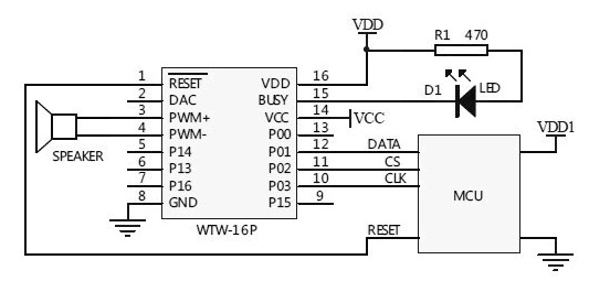
Three Line Mode=
I’ve taken the time to download sound clips, modify, and organize a few themes.
Games – sound effects for the mechanics and the animation, GLaDoS voices from the Portal video game
Spooky – selection of spooky sounds for Halloween projects.
LCARS – Star Trek computer phrases and sounds.
Zelda: Link To The Past – sounds from the video game.
Other themes online:
Star Wars Lightsaber sounds
Talking Clock
Alien Invasion Slot Machine uses the WT588D board for sound effects.
Parts:
Arduino Nano
Expansion Board
USB to mini USB ~ 5ft. cord
AC/DC Outlet Power Adapter
Project Box
WT588D Sound Module
8 x 7-segment Display module
(1-4) strips of 10 RGB 12mm LEDs.
(2) push-buttons
photocell
microphone
PIR sensor
Steps:
Prepare the following for wiring and connect to the expansion board:
WT588D with wiring harness and speaker
(1-4) strips of 10 RGB 12mm LEDs.
8 x 7-segment Display Module
(2) push-buttons
photocell
microphone
PIR sensor
Connect the push-buttons to the expansion board and upload test code.
Connect strips of 10 RGB 12mm LEDs to the expansion board and upload test code.
Connect the 8×7 segment display module to the expansion board and upload test code.
Connect the WT588D with wiring harness and speaker and upload test code.
Any sensor can be used to trigger specific or random sounds and going even further, a basic neural network could make decisions using multiple sensor inputs.
Connect the photocell to the expansion board and upload test code.
Connect the Microphone to the expansion board and upload test code.
Connect the PIR sensor to the expansion board and upload test code.

Completed SoundFXLight Project
Insert Arduino Nano into Expansion Board and plan to provide power using USB to mini USB cord. Optionally, AC/DC Outlet Power Adapter
Enclosing the project
Drill 7/16” – 1/2” holes into the project box:
HOLE 1: side
USB to mini USB ~ 5ft. cord
Optionally, AC/DC Outlet Power Adapter
HOLE 2: cover push-button
HOLE 3: cover push-button
top front side
HOLE 4: (1-4) strips of 10 RGB 12mm LEDs
HOLE 5: speaker connector
HOLE 6: side
microphone, PIR sensor
It takes time to learn how to use tools and equipment successfully, let alone, have the time to actually make the project meet your expectations. Time used for the project is time that could be spent with family, friends, learning something more important, etc.
You can purchase a completed SoundFXLight directly from me as a functioning example.

Arduino Pro-Mini directly connected to WT588D
Stay Tuned
Using Arduino to Make Motion Coming Soon!
Making Sound Effects with Arduino Sound and Voice Effects Sound plays an important role in the user experience by adding another layer of depth; making for a more realistic experience.
0 notes
Text
Space, Image and Sound: Bringing Everything Together.
This past week I’ve been assembling all my parts necessary to build the project itself. My one problem so far is getting the parts I need for the Arduino segment of the project because that requires a lot of learning and testing to get the circuit to work before building around it. I also need to find a suitable box for the DC motor.
For my project I’m going to be using Infrared Sensor/s (PIR Sensor) to turn the dc motor on/off when the hand gets near the box. I’ve started planning using the Fritzing software and I know how to connect the DC motor to it but I haven't finished the circuit that uses the sensor yet.
This has been an interesting project so far because I haven't used anything like an Infrared Sensor using Arduino before and it’s a great learning experience about the technology of Infrared Sensors and DC motors.
I do expect some roadblocks ahead in terms of the circuitry which I think is a good thing because I will be more prepared for if things don’t turn out magically correct.
Tutorial Videos:
https://www.youtube.com/watch?v=rIDwLlI3xo0
https://www.youtube.com/watch?v=By64MjWfbyk
https://www.youtube.com/watch?v=6Fdrr_1guok
https://www.youtube.com/watch?v=FxaTDvs34mM
https://www.youtube.com/watch?v=NZ1RHtF2rEA
1 note
·
View note
Video
youtube
PIR SENSOR TUTORIAL - WITH OR WITHOUT ARDUINO Just before creating my next projects tutorial, which will be using a PIR sensor, I thought I might create a separate tutorial explaining the working of a PIR sensor. By doing that I will be able to keep my other tutorial short and to the point. So, without wasting time let’s discuss what is a PIR sensor and how we can use it in our project.
Blog Post: https://diyfactory007.blogspot.com/2018/04/pir-sensor-tutorial-with-or-without.html
0 notes